Honeywell Fan Limit Control Wiring Diagram
Small fan for table or floor: Make l1 “hot” on 120v installation caution:
35 Honeywell Fan Limit Switch Wiring Diagram Wire Diagram Source Information

Limit switch wiring diagram products amp suppliers.

Honeywell fan limit control wiring diagram. 14 or 16 stranded wire, depending on electrical requirement. For control of high limit and fan motor in all types of forced air heating systems. Honeywell fan limit switch wiring diagram download.
Check the wiring diagram provided on the. Same as all the diagrams everywhere don t need add any of the resistors or other components from these diagrams. Honeywell fan limit switch wiring diagram.
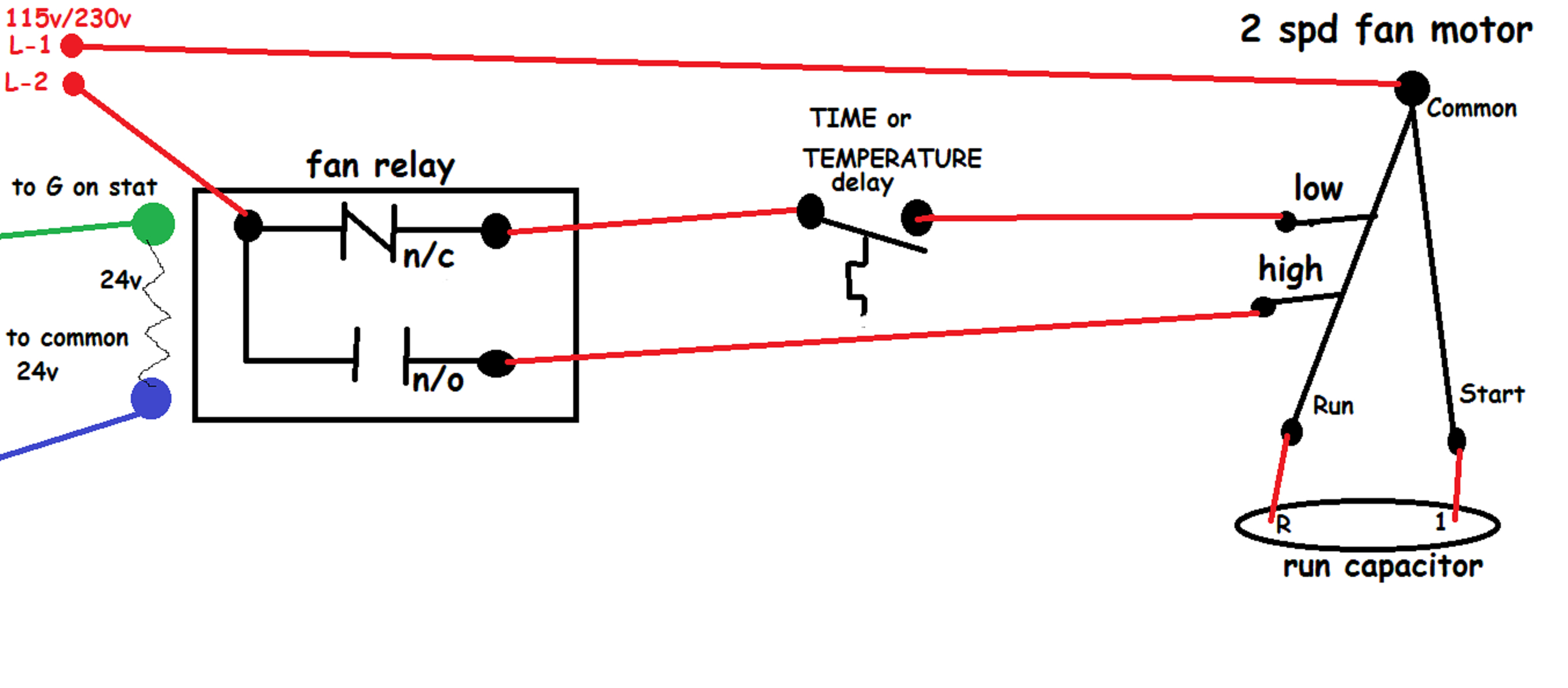
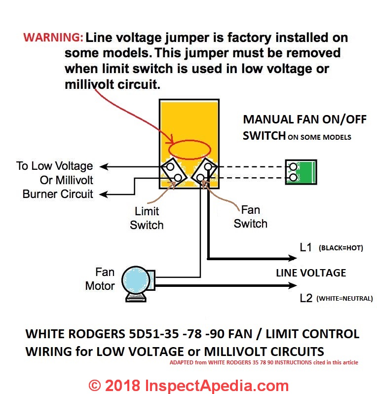
The honeywell turbo force air circulator fan has 3 speeds & a 90 degree pivoting head. 6 terminal toggle diagram in 2021 toggle switch electronic schematics basic electrical wiring. Limit switch fan switch fan motor optional remote manual switch for summer fan to low voltage or millivolt burner circuit diagram using limit in low voltage or millivolt circuit l1 line l2 note:
Female receptacles for 1/4 in. The push button is actuated by hand whereas the limit switch is operated mechanically. Is there a wiring diagram for the 40csfm 3 speed fan controller?
Unfortunately, there are no online records displaying the ignition switch wiring diagram for the john. Male flag connectors on both the fan and limit switches (fig. The electrical wiring used must also be rated for suitable temperature exposure (honeywell advises wiring rated for 167°f).
Cablemaster remote control wiring diagram. Interconnecting cord courses may be revealed about, where certain receptacles or fixtures. Please download these honeywell fan limit switch wiring diagram by using the download button, or right click on selected image, then use save image menu.
Fan limit control installation faqs honeywell temperature switch quality 101 how to install wire the controls on furnaces l4064b all white rodgers controllers old has 6 wires new 4 doityourself com community forums l6064 l4064b2228 b problem er shuts off too soon cycles and comes back within 30 seconds arnold s service company inc help diy home improvement… A wiring diagram is a streamlined conventional photographic depiction of an electric circuit. Compatible with heat pump systems.
R8285a1048 honeywell fan center relay transformer spdt 120v amre supply. Features three wiring terminal options available for easy installation: This one explains the 2 ways this switch can be wired.
Strip insulation from wires the distance shown by the strip gauge on the controller. Maximum ambient rating for s used with a. Interconnecting cord courses may be revealed about, where certain receptacles or fixtures have to be on a common circuit.
The manual includes a honeywell rth wiring diagram so if. Line voltage jumper is factory installed on some models. 14,16, or 18 solid wire or nos.
Wiring diagrams help technicians to find out how the controls are wired to the. This jumper must be removed when limit switch. How do i wire a ceiling fan going from two switches ( light & fan) to a single dimmer/fan control switch?
Print the cabling diagram off plus use highlighters in order to trace the signal. When you make use of your finger or perhaps the actual circuit with your eyes, it is easy to mistrace the circuit. 1 trick that we 2 to printing a similar wiring plan off twice.
Limit switch wiring diagram intended for honeywell fan limit switch wiring diagram, image size 697 x 453 px, and to view image details please click the image. And the sensing element can handle up to 350 °f. The following is a wiring diagram for a honeywell fan limit switch control.
Before beginning any wiring make sure you turn the power off. In other words you want to get rid of the 3 way system and just go to 1 switch controlling the fan. Limit switch wiring diagram intended for honeywell fan limit switch wiring diagram image size 697 x 453 px and to view image details please click the image.
Honeywell fan limit switch wiring diagram from i.pinimg.com print the wiring diagram off plus use highlighters to trace the signal. Wiring diagram for master flow thermostat. Assortment of honeywell fan limit switch wiring diagram you can download for free.
Turn the power off at the furnace and go a step further for safety and turn the power off at. L4029e acts as a fire thermostat in the ducts of ac & ventilating systems. Furnace fan limit switch how does a fan limit.
2018 10 01 john ford said. If the air temperature indicates a fire, the fan is shut down. Key switch wiring diagrams for lift master 02109 wiring.
Wiring diagram for light switch and outlet in same box. This quiet fan is compact.3 speed fan and heating/ cooling valve control. 1 trick that we use is to print exactly the same wiring picture off twice.
September 18, 2020 by faceitsalon. Wiring diagram master limit switch drreis de. When you use your finger or even the actual circuit with your eyes, it is easy to mistrace the circuit.
Cnc limit switch wiring diagram december 11 2020 1 margaret byrd. External limit switch kit for actuators in 2020 linear actuator actuator switch 2018 10 01 john ford said. We have accumulated several images, ideally this image is useful for you, and assist.
Please see the attached document on how to wire the 40csfm 3 speed fan controller. Honeywell fan limit switch wiring diagram wiring diagram for honeywell stc programmer new inspirationa. The switch portion of this honeywell fan limit control can tolerate 190 °f.
L4029e reset limit control opens a line or low voltage circuit if the air temperature reaches a critical level. The stc is a two channel 7 day programmer with. How to install and wire the honeywell l4064b combination furnace intended for honeywell fan limit switch wiring diagram by admin from the thousand photographs on the internet concerning honeywell fan limit switch wiring diagram, we choices the best libraries with ideal resolution just for you all, and this photos is usually among photographs series inside our.
Make sure the wires are properly tightened.
How to Install & Wire the Fan & Limit Controls on Furnaces Honeywell L4064B & All White Rodgers
Honeywell Fan Limit Switch Wiring Diagram Gallery

Honeywell Furnace Temperature Fan Limit Switch Control Heating

Honeywell Fan Limit Switch Wiring Diagram

3 Wire Limit Switch Diagram Wiring Library Honeywell Fan Limit Switch Wiring Diagram
Honeywell Fan Limit Switch Wiring Diagram Free Wiring Diagram

Collection Of Honeywell Fan Limit Switch Wiring Diagram Sample

How to Install & Wire the Fan & Limit Controls on Furnaces Honeywell L4064B & All White Rodgers

Honeywell Fan Limit Switch Wiring Diagram Fuse Box And Wiring Diagram

Honeywell Fan Limit Switch Wiring Diagram Free Wiring Diagram

Collection Of Honeywell Fan Limit Switch Wiring Diagram Sample

Honeywell Fan Limit Switch Wiring Diagram Fuse Box And Wiring Diagram

Honeywell Fan Limit Switch Wiring Diagram Free Wiring Diagram

Honeywell Fan Limit Switch Wiring Diagram Fuse Box And Wiring Diagram

Honeywell Fan Limit Switch Wiring Diagram Free Wiring Diagram

Honeywell Fan Limit Switch Wiring Diagram Gallery

Honeywell Fan Limit Switch Wiring Diagram Collection Wiring Collection
Honeywell Fan Limit Switch Wiring Diagram Gallery

Honeywell Fan Limit Switch Wiring Diagram Wiring Diagram